Automatic Roof Model Reconstruction from ALS Data and 2D Ground Plans based on Side Projection and the TMR Algorithm
Automatic Roof Model
Reconstruction from ALS Data and 2D Ground Plans based on Side Projection and the
TMR Algorithm
ABSTRACT
This paper presents an automatic roof model reconstruction method
based on the side projection of airborne laser scanning (ALS) data. The
proposed approach first detects the building’s primary orientation and decomposes
multi-layer roofs into a single one. Then, 3D structural lines are detected and
restored from the projected point clouds. Finally, a line-based roof model
reconstruction algorithm, namely TIN-Merging
and Reshaping (TMR), is proposed. The originality for 3D roof modeling is
to perform geometric analysis and topology reconstruction from two 2D
projections and then reshapes the roof using elevation information from the 3D
structural lines or ALS data. Experimental results indicate a nearly 100%
success rate for topology reconstruction can be achieved provided that the 3D
structural lines can be enclosed as polygons. However, the success rate of the Reshaping stage is dependent on the complexity
of the rooftop structure. With the exception of domed and multiple orientations
roofs, which are not considered in the developed method, we achieve success
rates around 92% to 95%. As for absolute accuracy, less that 50 cm of root-mean-square
error is observed in all X-Y-Z directions. The results demonstrate that the proposed
scheme is robust and accurate even when a group of connected buildings with
multiple layers and mixed roof types is processed.
Keywords: Roof Model Reconstruction, Topology Reconstruction,
Airborne Laser Scanning and Tin-Merging and Reshaping.
lTIN-Merging and Reshaping
The TIN-Merging and Reshaping (TMR)
algorithm is comprised of four main steps. The first one is a pre-processing
step to repair any measurement errors in input structural lines or imperfect
results from feature extraction. This can include performing right angle rectification, line
collinearity adjustment, snapping of dangles from shortening, and removal of
overhanging dangles. The second step is to construct a Triangulated
Irregular Network (TIN) using (Chew,
1987; Kallmann et al., 2003), where the vertices of structural lines are adopted as points and
the structural lines themselves are used for constraining the generated TINs. Two neighboring TINs are iteratively merged by removing
the shared edges that have no corresponding structural lines. The resultant
roof topology is reconstructed in a 2D projection. Finally, we reshape the roof structure based on the
rectified structural lines that contain the third dimensional information (Z)
to infer 3D roof models.
lPre-processing
Since the
imperfect generation of structural lines is unavoidable during the feature
extraction stage or during manual stereo-measurement, it is necessary to
correct them before the construction of TINs; otherwise some illegal TINs will
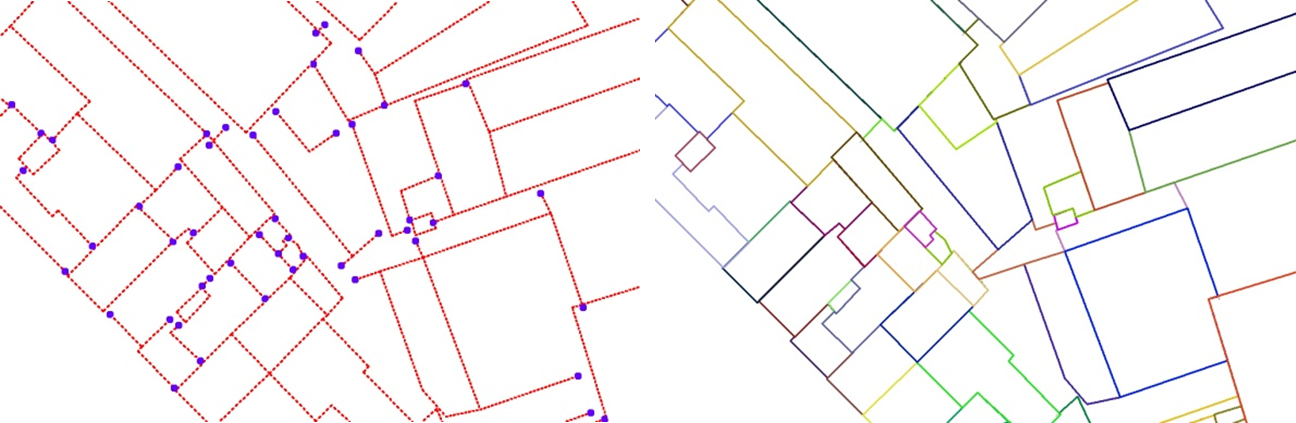
be generated. Fig. 10(a) depicts several examples of such deficiencies, in
which the red lines are the measured structural lines and the blue dots denote
the detected dangles. For example, a rectangular building might be skewed,
structural lines might pierce a wall or be disconnected from a neighboring
wall, two collinear-like lines might be distorted, multiple convergent lines might
be detached, and so on. Meanwhile, when dangles exist, some illegal triangles
will be generated and the topology reconstruction will fail. Thus, the pre-processing
of detected lines has to be robust and rigorous in order to successfully
reconstruct their topology. Fig. 10(b) shows the pre-processing results, i.e.
rectified structural lines, where the dangles were removed successfully. This
procedure can be performed fully automatically in the developed system after rational
determination of several adopted parameters,
the maximum dangle length, and the maximum rotation angle for right-angle
rectification.
Fig. 10. (a) Original measured (red) lines with dangles (blue); and
(b) the generated polygons (each in a different color).
lConstrained Delaunay
Triangulation
Delaunay
Triangulation (Delaunay, 1934) is a well-known technique
for constructing triangles from sparsely distributed points where there is no
fourth point inside its circumcircle to avoid spear-like triangles. Using this
technique unrelated points can be organized in such a way that neighborhoods are
connected with topology. Delaunay Triangulation is thus useful for topology reconstruction
of unrelated points. In this study, the primitive for roof model reconstruction
is derived from structural lines which have to be enclosed to define a polygon.
The generated TINs cannot intersect or cross over the structural lines. The endpoints
of the structural lines act as points for constructing TINs on the 2D
horizontal plane but are constrained by the structural lines themselves using Constrained Delaunay Triangulation(Chew, 1987; Kallmann et al., 2003) to avoid triangles
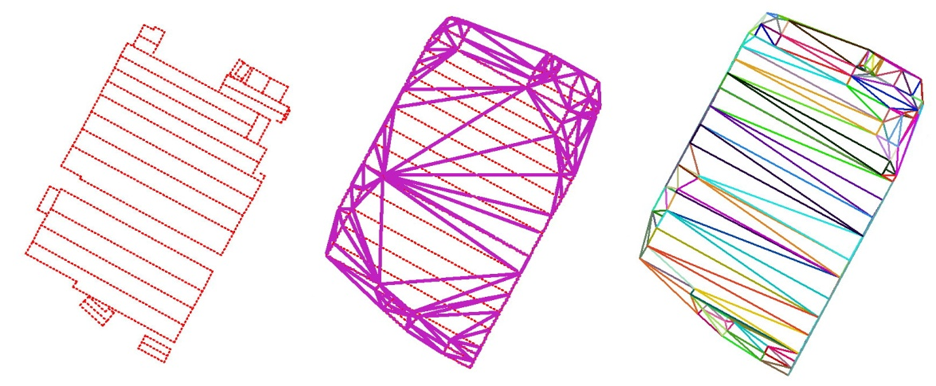
crossing the structural lines. Fig. 11 illustrates the effect with and without
applying the line constraint in the generation of TINs. Fig. 11(a) shows the
input lines and Fig. 11(b) shows the generated TINs without the line constraint.
One may notice that some created triangles have crossed over the original
lines. Fig. 11(c) illustrates the results after applying the line constraint.
It is obvious that the use of the line constraint for TINs generation can
achieve reasonable and correct topology.
Fig. 11. Delaunay Triangulation with and
without line constraint.
lTIN-Merging
After the
generation of TINs, the relationship among the structural lines is created. The
TINs are described in convex hull. Some of them appear around concave building
boundaries do not exist in the real world and should be removed in advance.
Meanwhile, some shared edges between two TINs that do not exist should be eliminated
as well. This can also reduce the volume of data storage and present rational
roof models. The clue for the detection of existing edges is these rectified structural
lines. We can merge two neighboring TINs by erasing the shared edge that has no
corresponding structural line. The TIN-Merging
procedure is thus an iterative loop used to check for shared edges between two
TINs (or polygons) to verify whether there is any overlap or collinearity
between the shared edges and the rectified structural lines. If there is no
corresponding line, the shared edges will be removed and those two TINs (or
polygons) are merged as one polygon.
Fig. 12
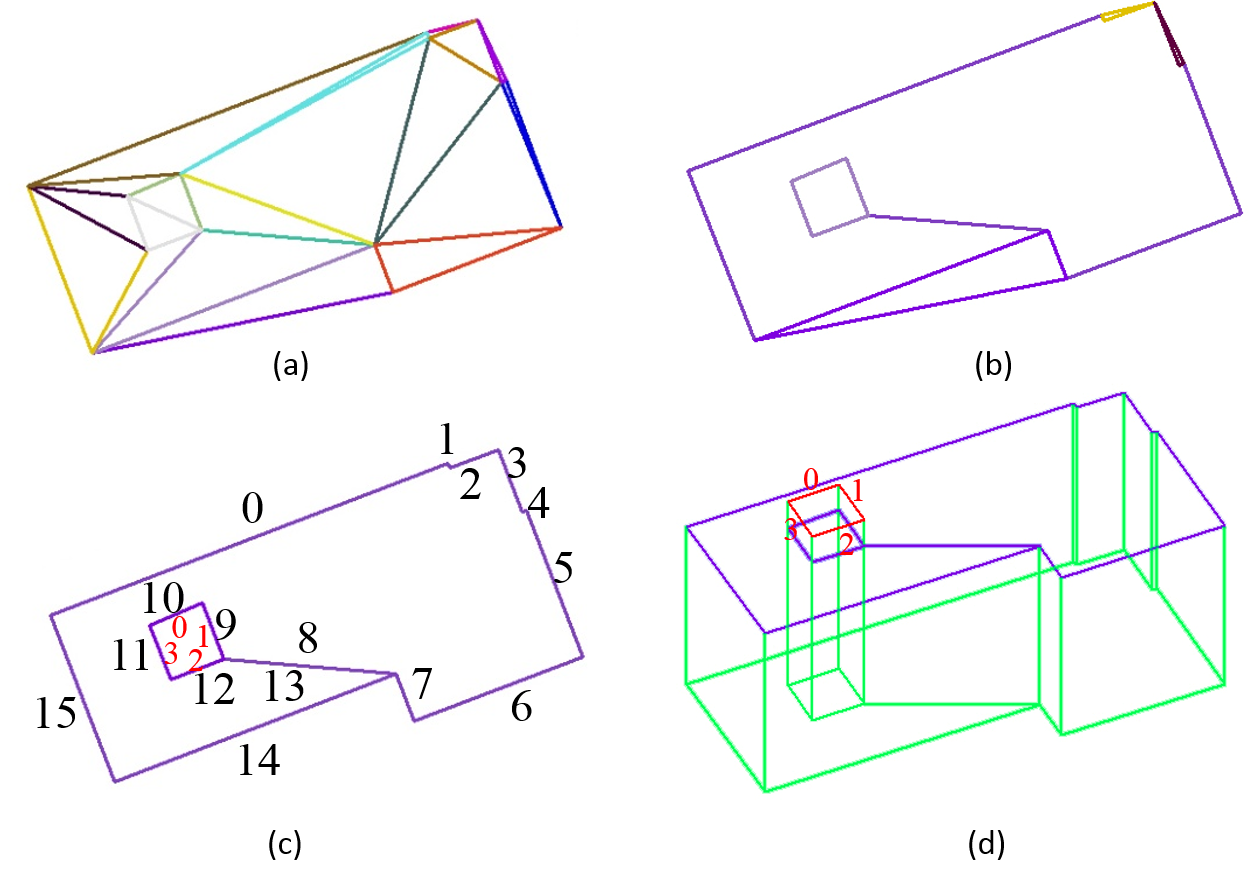
shows an example of TIN-Merging. The CDT results are shown in Fig. 12(a). Fig.
12(b) is the results after applying TIN-Merging and Fig. 12(c) shows the
results after removing the outer TINs that do not exist in the real world. It
can be seen in Fig. 12(c) that there is a small roof surrounded by another,
thus two additional pseudo edges
(same location but different directions) are added to connect each other. The
edge sequence numbers are denoted. Line numbers 8 and 13 are two pseudo edges that have no corresponding
structural lines but are kept to describe this donut-type polygon. Since two
polygons should not overlap after topology reconstruction, the inner polygon
has to be encircled by the outer one. It means that the outer polygon has to be
cut by the inner one resulting in a donut-type polygon. One may compare the 3D
view in Fig. 12(d) for clarification.
Fig. 12. Example of the TIN-merging process.
lReshaping
Before
reshaping, recalling that all the above procedures are processed in two-dimensional
space. This reshaping procedure
utilizes the third dimensional information (Z) from the endpoints of rectified
structural line or ALS data to infer the final shape of the roof structure.
The basic
idea behind constructing a roof shape (whether flat or inclined) from 3D lines
is that two connected lines will have the same 3D coordinates at their joint
and form a triangle. A triangle always located on a plane. The parameters of a
planar function can thus be calculated by the vertices of the triangle.
In the
beginning, all edges are classified as independent,
shared or pseudo edges. The pseudo edges are created during the
construction of Delaunay Triangulation as described in the previous section. An
independent edge means that no
neighbor polygon is connected, but a shared
edge has. For example, edge numbers 9 to 12 in Fig. 12(c) are shared edges while the other edges (with
the exception of edge numbers 8 and 13) are independent
edges. The height value for an independent edge can be initialized and fixed by
the Z-value of its corresponding 3D line terminals. On the other hand, the
height value for the shared edges and pseudo edges can only be initialized, but is not yet fixed.
At the
second stage, a coplanar verification process is applied for all edges within a
polygon. This step is particularly essential for a roof that is taller than its
surrounding roofs. In the previous stage they are assigned as shared edges, such
as the inner roof depicted in Figs. 12(c) and 12(d) highlighted by the red numbers
0 to 3. If all the edges of this polygon are located on a plane, they will be
classified as independent edges with fixed heights. It is worth noting that
currently edge numbers 9 to 12 in Fig. 12(c) are still remained as shared edges. On the other hand, for a
gable roof, the ridge lines are first considered to be shared edges. They will be considered as independent edges by applying this coplanar verification process.
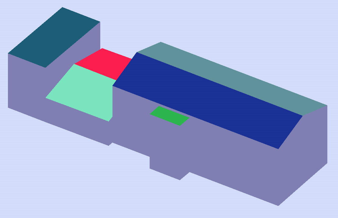
Fig. 13 illustrates a gable roof (the rightmost one) and a flat roof (the leftmost
one) whose shape is determined at this procedure. In the figure, the independent edges are depicted in yellow
and the shared edges in white. The
shape of the gable roof in the middle and the small flat roof cannot be determined
in the current stage, because the initial heights of the shared edges are
assigned by its neighborhood that is taller and will cause non-planar
situation.
The third
step of reshaping is to search for the existence of independent edges within a
polygon. Once more than two independent edges are found, the least-squares
adjustment can be applied to calculate the plane equation for this polygon and
to determine the heights of the other shared edges. These two independent edges
can be connected or parallel to each other to form a triangle or a rectangle as
long as they fall on a plane. The height value of the other shared edges will
be adjusted and their attribute will be reassigned as independent edges. The smaller flat roof shown in Fig. 13 is an example
of this case. Since three of the edges are independent, the height of the
remaining shared edge can be decided and fixed directly by least-squares
adjustment.
Fig. 13. Example of independent (yellow) and shared (white) edges.
The
developed algorithm is designed for 3D structural lines derived from any source,
such as manual stereo plotting (Rau and Chen, 2003), stereo line matching (Schmid
and Zisserman, 1997; Park and Zimmermann, 2000), ALS data (Chen et al.,
2008), and so on. With the above inference procedures, in most cases, the roof
models can be reconstructed successfully. However, if it is human error that
causes structural lines to be missed, i.e., the roof boundary is not closed,
the inference process may fail. One example will be demonstrated in the case
study with two exceptions are found as stated below.
i.The first is for a donut-type
building, where the height of the inner roof is either lower than the outer
roof or is empty. Occlusion problems make it difficult to recognize and to
delineate its boundaries, in which case they will be kept and decided by the
operator. One example will be discussed in the performance analysis.
ii.The second is for a polygon
with only one independent edge remaining after the whole process. In this case,
an exhaustive test will be performed to examine any two lines within the
polygon, by checking their co-planarity. If any two of them fall on a plane,
all of the other edges will be adjusted using this plane equation and their
attributes will be reassigned as independent
edges. The middle gable roof shown in Fig. 13 illustrates this situation. Although
its ridge line is a shared edge, its initial height is assigned by its
corresponding 3D line and is coplanar to the independent edge in 3D space. If the
above conditions are not all satisfied, this roof will normally be assigned as
a flat roof using the only independent edge. However, it is suggested that the
result should be checked again by visual inspection or utilize the ALS data for
reshaping, as will be discussed in the following section, in order to complete
the roof modeling procedure.
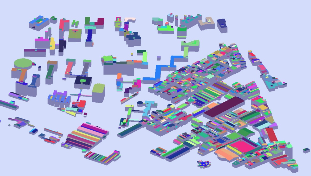
Generated 3D building models for test dataset I.
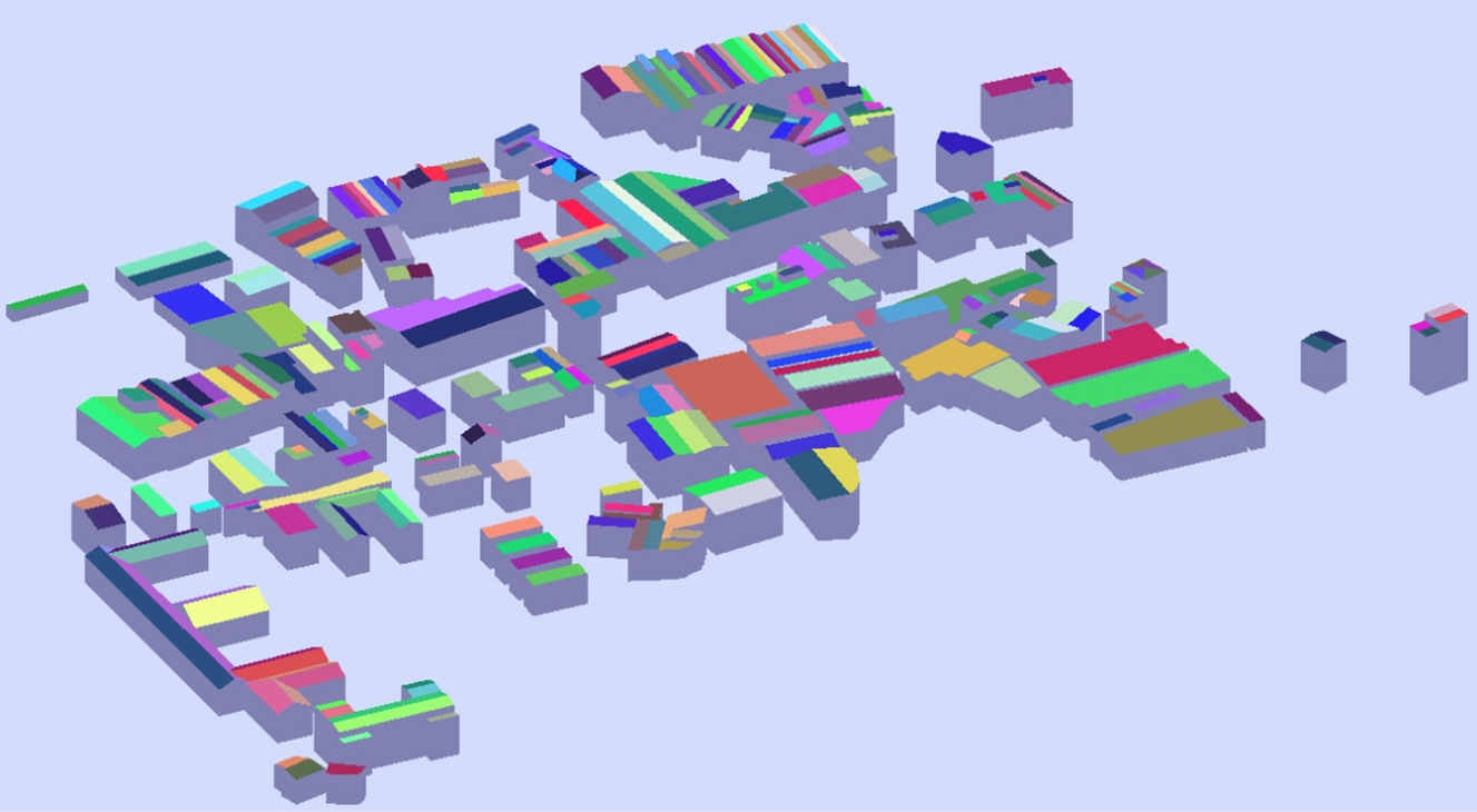
Generated 3D building models for test dataset II.
國立成功大學
測量及空間資訊學系 Department of Geomatics, National Cheng Kung University